
Summary of Test
ASTM F1566 test methods evaluate mattress components, innersprings and boxsprings and mattress sets. Component innerspring and boxspring test methods include measurements of firmness, firmness retention, durability, and effect of impact. Mattress and mattress set test methods include measurements of firmness, firmness retention, durability, effect of impact, and height change. These methods are intended to be used on newly manufactured products.
In the mattress industry, the fundamental goal is to develop a mattress that will maintain quality and retain firmness over a long period of use. The Cornell Test within ASTM F1566 was created to measure two critical elements of a mattress, firmness retention and surface deformation, at various cycle points from 0 to 100,000 cycles in efforts to simulate mattress performance after approximately 10 years of use.
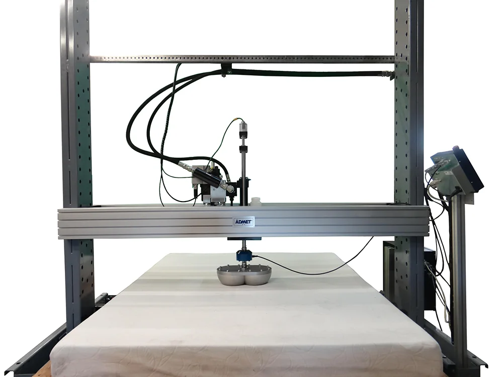
ADMET’s H-Frame Cornell Mattress Tester is designed to perform the Cornell Test with minimal need for operator interaction. The system comes equipped with a specialized controller in which the user specifies the desired cycle points and initiates the test. The system then cycles between two forces per the specification, and automatically takes measurements at the specified cycle points. Upon test completion, a report displaying the force values at specified deflections for each cycle point is generated for calculation of surface deformation and firmness retention.
Before conducting ASTM F1566, it is important to read the entire specification in the relevant ASTM publication.
Recommended Equipment


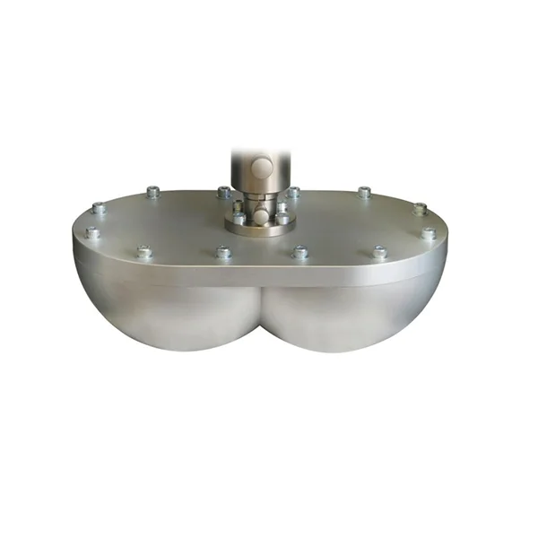
Testing Procedure
Firmness Retention and Surface Deformation – Cornell Test Procedure
- Insert mattress onto the test frame and slide actuator as necessary so that the desired test location is under the ram head.
- Specify up to 8 cumulative cycle points for the machine to record force deflection data.
- Initiate the test by pressing “start”.
- Allow the system to cycle through the test and take measurements at user specified cycle points.
- Open test completion, view and analyze the generated test report.
Firmness Rating Test Procedure A: Testing Innersprings and Flexible Foundations
- Place the un-upholstered mattress core of flexible foundation unit onto a rigid, flat platen. Platens must have a diameter of 344 ± 5 mm (13.54 ± 0.2 in).
- Run the test at a constant speed as described and illustrated in the standard. At each location, determine resistance values in 2 N (0.5 lbf) increments at 12.5, 25, 38, 50, 63, and 76 mm (0.5, 1, 1.5, 2, 2.5, and 3 in) of deflection of the top surface for innersprings and 12.5 mm and 25 mm (0.5 and 1 in) of deflection of the top surface for flexible foundations.
Firmness Rating Test Procedure B: Testing Mattresses
- Place the mattress or the mattress set onto a rigid, flat platen. Platens must have a diameter of 344 ± 5 mm (13.54 ±2 in).
- Run the test at a constant speed as specified in the standard.
- Preflex the area to be tested. Allow the sample to rest for 6 min after preflex.
- Preload the sample Record overall height once force is applied. Record resistance values in 2 N (0.5 lbf) increments at 12.5 mm intervals until a 778 N (175 lbf) load is reached.
Durability Test Procedure A: Testing Innersprings or Boxsprings
- Prepare the samples and the foam pad assembly as described in the standard.
- Use a comparative analysis to test and compare the durability of materials.
Durability Test Procedure B: Testing Mattresses
- Prepare the sample as described in the standard and measure the initial height.
- Using the juggernaut roller, start the test. The maximum stroke of the roller should equal to the width of the mattress minus the width of one flat side of the roller.
- Run the test for a total of 100,000 cycles. Once the test is terminated, allow the sample to recover for 60 minutes.
- Determine the final firmness rating and the final height of the specimen.
Impact Test Procedure
- Prepare the samples as described in the standard. Measure the initial height.
- Select drop locations to compare performance at various positions.
- Drop the 356 mm (14 in) diameter platen with a total mass of 79.5 kg (175 lb) from a height of 25 mm (1 in) above the surface of the mattress at the specified positions. Measure the heights of the specimen at these positions.
- Repeat the drop test at 25 mm (1 in) increments until there is a 19 mm (0.75 in) permanent deformation or structural failure.
Firmness Retention and Surface Deformation Test Procedure
- Prepare the sample and place it on a rigid flat surface as described in the standard.
- Raise the ram head to the top of the stroke and rotate the eccentric.
- Lower the ram head and the shaft until a test load of 1025 N (230 lbf) is reached. Return ram head to the initial “up” position, then lower it again until 22 N (5 lbf) is reached.
- Adjust static scale to zero. Lower the ram head until 1025 N (230 lbf) is reached. Record the static reading for the test load.
- Raise the ram head and rotate the eccentric once more and adjust the stroke scale to the final static scale reading obtained in the previous step.
- Rotate the eccentric at the top of the stroke and reset the ram head and shaft so that displacement is at zero.
- Run the test for 200 cycles at 100 ± 5 strokes/min.
- Stop the machine with the eccentric at the top of the stroke and lower the ram head until 1025 N (230 lbf) is reached. Return ram head to the initial “up” position, then lower it again until 22 N (5 lbf) is reached.
- Reset the static scale to zero.
- Lower the ram head and record the load, obtaining readings for each 12.7 mm (0.5 in) increment until 1025 N (230 lb) is reached. Record the static scale or deflection reading for the test load at each increment.
- Reset the ram head and shaft so that there is zero deflection.
- Run the test for at least 6000 cycles at 100 ± 5 strokes/min.
- Stop the machine with the eccentric at the top of the stroke and lower the ram head until 1025 N (230 lbf) is reached. Return ram head to the initial “up” position, then lower it again until 22 N (5 lbf) is reached. Record the deflection data and call this reading the “additional dimple”.
- Repeat steps 9-13. This time instead of 6000 cycles, run the test for a total of 12,000 cycles.
- Repeat steps 9-13 at 25,000, 50,000, 75,000, and 100,000 cumulative cycles.
- At the end of tests, plot the load deflection curves at each cycle.

Just Ask!
Questions about running ASTM F1566 on your system?


